Wiring part 1: Introduction
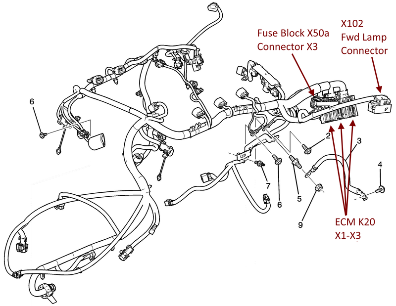
Since I’ve got some time before I spend a bunch on hardware and tools I figured I’d go ahead and get started on the wiring. It’s mostly information gathering and planning so it makes sense to do it now. At a high level we need to interface the stock LFX harness:
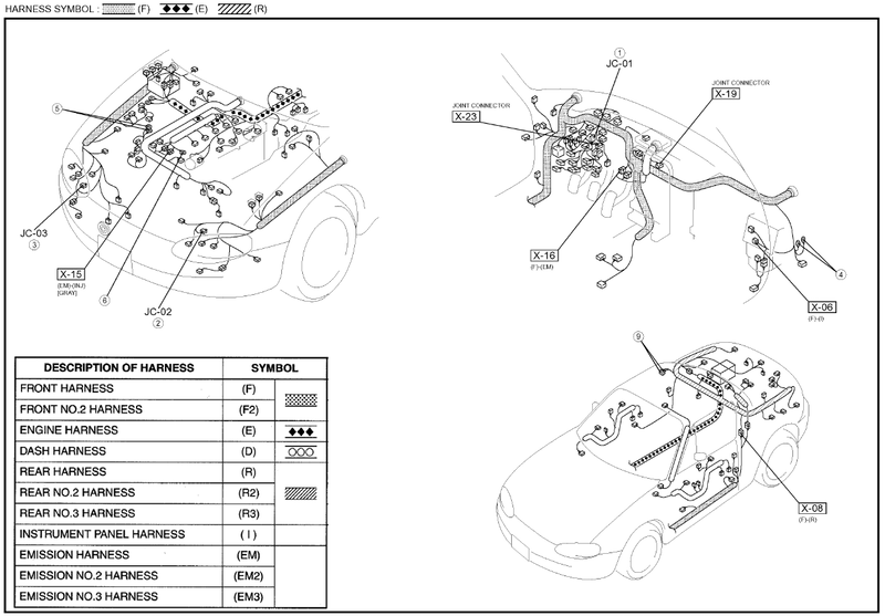
With the Miata chassis harnesses:
Going into this I thought the Mazda engine harness would be like every Honda I’ve worked on, in that the engine harness would disconnect from the chassis at a few points and the whole engine + harness would come out. It would be easy, then, to leave the chassis-side harnessing in place in case I needed anything in the future and simply add the stand-alone LFX wiring.
Mazda decided to take a different route and build the engine harness into the chassis, which makes our integration significantly more complicated. Your choices are either cut, insulate, and pretend the unnecessary engine wires don’t exist, or depin and remove them entirely from the engine harness. Because of the classic “I’m in there anyways” argument I’m planning on removing \ depinning the unnecessary wires from the engine harness (up to the point that I don’t have to take the entire chassis harness apart).
Fortunately the LFX harness is pretty self-contained in terms of running the engine, although there will be a few points that the two harnesses need to touch. My objective is to keep the two systems as separate as possible to minimize work and maximize documentation re-use – I’m ok with a few additional pounds of unnecessary wiring to save myself tens of hours of work, not to mention debug time if I get it wrong.
To run the engine, the chassis needs to provide the engine harness with:
- Always-on battery voltage
- Switched battery voltage
The engine harness needs to provide the chassis (separate from the chassis harness) with:
- CAN bus (to gage cluster & OBD2 port)
- Throttle pedal wiring
- Power to the fuel pump relay (enables re-use of Miata fuel pump wiring)
Because we’re not using the Camaro fuse box (which is truly enormous, google it), we’ll need to add a new fuse and relay box that controls:
- AC compressor
- Fans
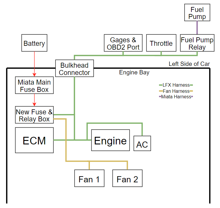
At a very high level, this is how I’m planning on interfacing the two systems:
Detailed planning starts with good schematics for both the Miata and Camaro. Miata chassis wiring changed every 2 years for the NB, so it’s important to start with the correct wiring diagram for your car. The Mazda ones are way better:
- 1999-2000 (source)
- 2001-2002 (Attached. I downloaded from OPL (below), merged, labeled, and bookmarked the PDF)
- 2003-2005
The Camaro manual is huge (~100Mb) so I’ll share it from my google drive. I wish there was a more reliable place to keep it, though – if you feel like hosting it don’t hesitate to reach out 🙂
The next step, now that I’ve got a more clear idea of what I’ll be doing and I have the appropriate schematics, is to pull the Miata engine and start stripping back the harness. I’ll make another post detailing that process, which will likely take way longer than the LFX-side. In parallel I’ll start designing the LFX harness modifications.
References:
- Gooflophaze’s post on harness tools
- Gooflophaze’s post on the LFX harness pinout \ modifications
- Goodwin Racing’s post on his bespoke harness build
- How to access factory wiring manual through the ohio public library
- Alternately, go here: https://ohioweblibrary.org/sources/
- Click on Chilton Library, or https://ohioweblibrary.org/db/chilton and use library card 123456789
- I followed these steps and merged all the individual pdfs into one, then added bookmarks.
- Post with a bunch of non-mazda wiring daigrams
- LFX pinout spreadsheet
