It's Better With Arduino


Leave a comment

LFX Swap: Wiring Part 2

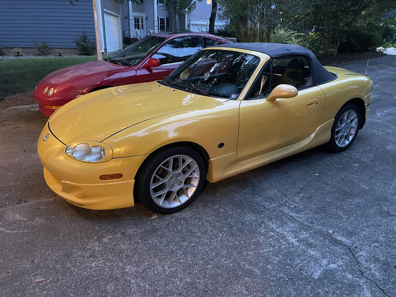
Had a productive weekend and removed the drivetrain despite the 101°F heat index (!). I put the chassis on wheel dollies and tucked it away in front of the other two cars. It’s not exactly easy to get to, but it’s easier than it being outside.

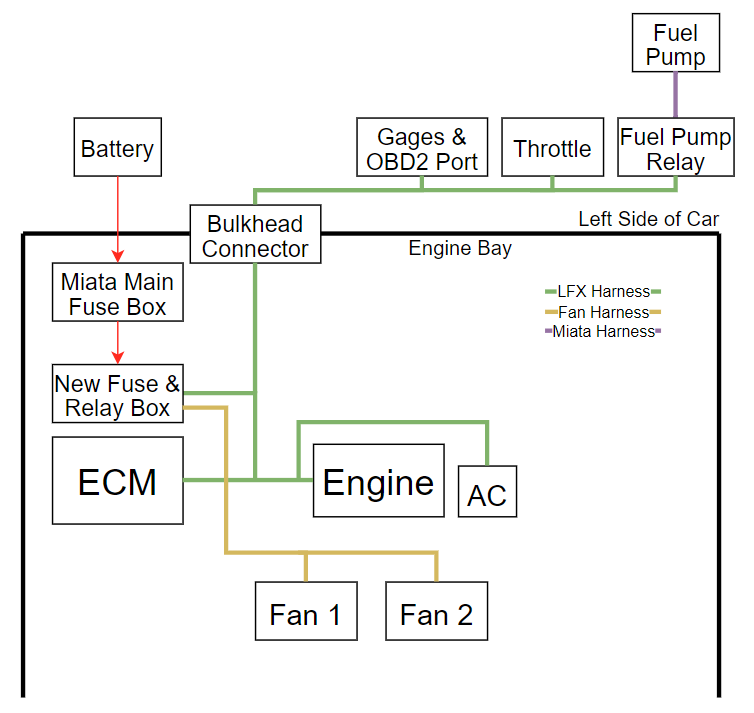
In parallel I’ve been working on the wiring – I’m starting with a high level block diagram, now on revision 3:

There are three functions where the Miata and new harnesses interface:

  • Fuel pump
  • AC compressor
  • Fans

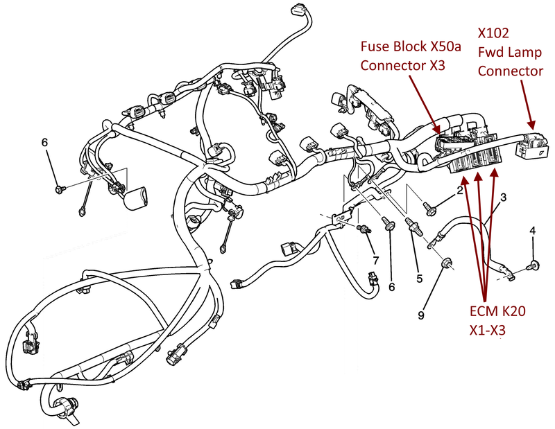
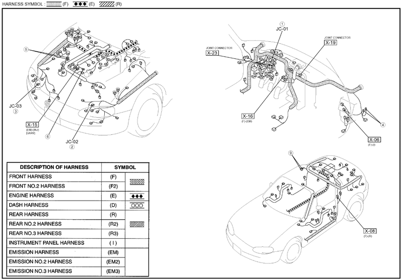
Fortunately there is an emissions connector in the Miata harness, x-16, where the AC “command compressor on” signal and fuel pump relay coil are present. Ideally I’ll be able to connect my interior harness to this connector and avoid splicing into the Miata harness. Obviously I’ll be modifying it pretty significantly anyways, but it should draw a clean line between the two systems.

The Miata PCM grounds the fuel pump relay to enable it, and the other side of the coil is connected to switched power through the main relay. The e39 uses a return-less system and controls the fuel pump speed via a PWM signal to the fuel pump control module. I should be able to re-use the stock Miata fuel pump relay by connecting the non-x-16 side of the relay coil to ground and connecting the e39 fuel pump PWM signal to x-16. @rdb138 used this approach and it’s worked fine for him – I’ll probably add a flyback diode across the relay in case the e39 output isn’t protected.

For the AC compressor, I’ll probably take the same approach @gooflophaze did and wire up a “dumb” AC compressor control circuit. I looked into using the e39 output, which would be nice since it compensates for the added load and turns the fans on, but it would require the HVAC control module or knowing what message to send the e39. Since I don’t have a Camaro, I’ll take the “dumb” approach for now. If anyone knows what message to send the e39 to turn the AC compressor on, I’m all ears 🙂

The fans are probably the easiest since the e39 has relay control outputs. Those will get wired in a low\high speed configuration similar to the Camaro.

Alternator control is another question I need to address – the e39 controls the field coil (and therefore how much voltage the alternator produces). The ECM determines how much voltage the alternator should produce based on a “battery current sensor” in the “battery housing” (according to the Camaro schematics), which I obviously won’t have. I believe @gooflophaze is working on a control module, but I don’t think it’s ready yet. Others have replaced the factory alternator with a simpler alternator, but according to gooflophaze if you just disconnect the alternator connector (not the wire) it should fall back to 13.8V. It’s not perfect, but it’s probably good enough.

I think I’ve accounted for all of the signals, so now it’s on to making schematics for each of the new harnesses and picking out connectors. I’m a little worried about putting the throttle pedal through a connector since @ThePass (and @rdb138 , I think) had issues with any sort of noise putting the ECM into “safe” mode. I’ll start out with a good, aerospace-grade connector and if I run into issues, I’ll bypass the connector and run straight from the ECM to the throttle pedal.

I’ve seen others (@griff ?) connect a flex fuel sensor into the e39 but I’m not sure where it gets connected – I’m guessing through the AC pressure sensor input?


Leave a comment

LFX Swap: Wiring Part 1

Wiring part 1: Introduction

Since I’ve got some time before I spend a bunch on hardware and tools I figured I’d go ahead and get started on the wiring. It’s mostly information gathering and planning so it makes sense to do it now.  At a high level we need to interface the stock LFX harness:

With the Miata chassis harnesses:

Going into this I thought the Mazda engine harness would be like every Honda I’ve worked on, in that the engine harness would disconnect from the chassis at a few points and the whole engine + harness would come out. It would be easy, then, to leave the chassis-side harnessing in place in case I needed anything in the future and simply add the stand-alone LFX wiring.

Mazda decided to take a different route and build the engine harness into the chassis, which makes our integration significantly more complicated. Your choices are either cut, insulate, and pretend the unnecessary engine wires don’t exist, or depin and remove them entirely from the engine harness. Because of the classic “I’m in there anyways” argument I’m planning on removing \ depinning the unnecessary wires from the engine harness (up to the point that I don’t have to take the entire chassis harness apart).

Fortunately the LFX harness is pretty self-contained in terms of running the engine, although there will be a few points that the two harnesses need to touch. My objective is to keep the two systems as separate as possible to minimize work and maximize documentation re-use – I’m ok with a few additional pounds of unnecessary wiring to save myself tens of hours of work, not to mention debug time if I get it wrong.

  To run the engine, the chassis needs to provide the engine harness with:

  • Always-on battery voltage
  • Switched battery voltage

The engine harness needs to provide the chassis (separate from the chassis harness) with:

  • CAN bus (to gage cluster & OBD2 port)
  • Throttle pedal wiring
  • Power to the fuel pump relay (enables re-use of Miata fuel pump wiring)

Because we’re not using the Camaro fuse box (which is truly enormous, google it), we’ll need to add a new fuse and relay box that controls:

  • AC compressor
  • Fans

At a very high level, this is how I’m planning on interfacing the two systems:

Detailed planning starts with good schematics for both the Miata and Camaro. Miata chassis wiring changed every 2 years for the NB, so it’s important to start with the correct wiring diagram for your car. The Mazda ones are way better:

  • 1999-2000 (source)
  • 2001-2002 (Attached. I downloaded from OPL (below), merged, labeled, and bookmarked the PDF)
  • 2003-2005

The Camaro manual is huge (~100Mb) so I’ll share it from my google drive. I wish there was a more reliable place to keep it, though – if you feel like hosting it don’t hesitate to reach out 🙂

The next step, now that I’ve got a more clear idea of what I’ll be doing and I have the appropriate schematics, is to pull the Miata engine and start stripping back the harness. I’ll make another post detailing that process, which will likely take way longer than the LFX-side. In parallel I’ll start designing the LFX harness modifications.

References:


Leave a comment

Miata LFX Swap Intro

I’m mirroring my build thread here for my hoards of ardent followers (and also in the event miata-turbo goes down). Enjoy!

I finished grad school in December, so naturally my reward to myself is another long term project :D. I’ve wanted a car project for as long as I can remember, but my learning addiction has made it difficult to do much more than maintenance and bolt-ons. I decided on a LFX-swapped Miata because it’s a decent project fab-wise, reasonably priced for the performance, and documented well enough that I won’t be entirely breaking new ground. Enter my chassis: a 102k-mile 2002 SE in Blazing Yellow. It came with a thick stack of service records that almost makes me feel bad about modifying it.

Behind: the reason I can afford this project, my 312k-mile 98 Integra that (I won’t let) die

My goal is to build a car that’s comfortable enough for a 4-hour road trip and is also capable for the occasional track day. I’d like to drive it on a regular basis, and I know if it’s super uncomfortable I’ll only drive it a few times a year (been there, done that. It’s too hot in NC to not have AC). Drivetrain-wise this means AC, power steering, an exhaust system that doesn’t make my ears bleed, and soft-ish engine mounts.

Now that I’ve got a chassis I need to:
1. Pull and sell the engine, transmission, diff, and whatever odds and ends people will buy
2. Source and buy an engine, transmission, and diff
3. Buy a welder
4. Buy the V8R kit, harness, ECM,…

Step 1 is cash positive, whereas the remaining steps require a lot of investment up front. I’m hoping that selling the existing drivetrain will cover most of the cost of the LFX, but I’ll need to save for the welder and V8R kit. While I’m saving, I’ve taken the opposite path of most other builds and started on the wiring first. I’ll make a separate post on that soon. Anyways, I’m planning on documenting the build process here for others (as well as myself for when I forget details in a month) and I wanted to introduce myself!

I’ll try to post my references when they’re useful, below is a list of build threads that were super helpful in researching the process: