Wiring part 3: Design
I’ve spent more time planning the wiring than I care to admit, but I think the results were worth it. I’ve broken this post down into two sections, removal of the old stuff and design of the new stuff. Wiring supplies cost ~$550 after tax and shipping, so buying a pre-made harness for $1200 is a deal! I chose to roll my own since the pre-made harness doesn’t include control for the fuel pump, fans, or AC compressor, plus I’ll feel more comfortable having a schematic and better understanding of how it all fits together.
Removing the old stuff: factory wiring
Removing the factory wiring was easier than I was anticipating, just time consuming. Engine and chassis harnesses are mostly separate and interface at two connectors, x-16 and x-24 (in my 02, other years may be different). X-24 has fuel tank signals on it (tank level, pressure, etc.) and x-16 has everything else. I thought the engine harness in earlier years were bundled with the chassis harness, but at least for my car I was wrong.
I started removing the unnecessary stuff from the chassis harness by first labeling all the things I didn’t need (cruise control, immobilizer, fuel pump, fan, and AC compressor relays, clutch interlock switch, diagnostic port, etc.) and depinning those connectors. I traced those wires back to where they terminated on the other end – either a crimped butt connection in the harness or another connector – and removed the wire there. It was a ton of unwrapping 20 year old electrical tape, so some disposable gloves came in handy. A right-angle pick was also helpful to tear electrical tape without damaging wires in the event I couldn’t find the end to unwrap it. After all was said and done I was left with approximately 3 gallons of used electrical tape

Air bags
My intention going into this was to keep the airbags since this is a street car. The more I thought about it, though, I really wanted an aftermarket steering wheel, which would disable the air bag system anyways unless I faked it out with a resistor. Who knows what the system would do in a crash with a resistor installed – it may or may not work. I concluded that it made sense to remove the whole system, which I wasn’t super excited about, but it makes logical sense. Most of this was pretty simple, the controller sub-harness connects to the chassis through connector S1-05. There were wires directly from the controller to the drivers and passenger air bags, but those were easy enough to remove since everything was apart.
A very important piece of information I learned after the fact – apparently the factory NB seatbelts have a collapsible member which allows more body motion in a crash, and is designed to work in conjunction with the airbags. More body motion without airbags seems like a bad idea, so I’ll be replacing them with NA seatbelts and cutting the loop in the drivers-side belt. This is apparently the configuration that non-SRS NA’s got. Feels like a step backwards safety-wise, but that aftermarket steering wheel tho.
I ended up removing about 10 lb of factory wiring, including engine harness:

And the engine bay after factory wiring removal and re-wrapping with tessa tape: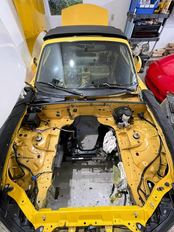
New harness design
I’ll write this assuming you’ve already read gooflophzes LFX harness and electrical tools posts. As I mentioned in my first post, my objective was to make the LFX stuff as standalone as possible and have a few, clearly defined and easily separatable interfaces with the chassis harnessing. After sifting through both the LFX and Miata wiring diagrams I created the attached schematic. If (probably when) this gets revised I’ll keep this post up to date.
I then had to pick out individual components, which was probably harder than the schematic since there are many details and I was designing and sourcing at the same time. The outcome is the attached BOM, which includes just about everything you’d need to build this from scratch. I compared prices from all 4 suppliers, so the price reflected is as close to the minimum as I could get. The BOM and schematic tell you the “what”, and I’ve included the “why” for my design decisions below.
Powertrain relay
I used the same powertrain relay as gooflophaze since I’ve been told the factory main relay is a weak point. It provides fused power, both switched (controlled by the factory main relay) and unswitched to the LFX harness, fans, and fuel pump. It’s also a convenient point to disconnect power via the ring terminals.
Inertia switch
I’ve seen others use inertia switches on their fuel pump relay and it seems like cheap insurance in the event of a crash, so I included one on my build as well. Since the fuel pump is switched through the powertrain relay I wired this in series with the powertrain relay coil. I could have wired it in series with the fuel pump relay coil but it would have made that wiring more complicated, plus there’s not a big difference between killing power to the entire engine vs just the fuel pump.
Wire
For automotive applications most people either use Tefzel or TXL (XLPE) wire. Tefzel -32 is what gets used in aerospace and motorsport due to its higher temperature rating (150°C vs 125°C), better abrasion resistance, thinner and lighter insulation, and higher electrical conductivity than TXL. The drawback, however, is that at the time of writing it’s about 2.25x the cost for a 1000ft spool and much more for smaller lengths. Since factory wiring is TXL I didn’t see much benefit in spending the extra money on Tefzel for this project.
I did end up using MIL-22759/16 wire for the fuel pump, but that decision was driven by the max wire OD on the connector I chose. Doing it over again I’d just re-use the factory Miata wiring – the DW200 draws something like 10A which is well within the limits of the factory wiring.
Bulkhead Connector
I could have extended LFX harness wires and ran them through the existing firewall grommet but it would have made removing the engine much more difficult. I’ve worked with Amphenol circular connectors before so I pieced together a kit from Digikey. I thought it was going to save money, but it ended up costing about the same as kits available from places like Ballinger. The advantage, though, is that I got exactly what I wanted and I’ll end up with spare parts in case I need to repin something. I also was able to get the bulkhead-side connector in a flange mount version, the connector Ballinger sells requires a D-shaped cutout which would be difficult to make in the firewall.
I chose the ADHP series of connectors because they’re designed for harsh industrial environments (agricultural underhood, -55°C to 125°C), are reasonably priced ($60 for both shells, pins, and backshells, without spares), and have a high contact density. There’s an identical series of metal-bodied connectors (ADHM) that’s a little more expensive, but there isn’t a flange-mount option – they only mount in a D-shaped cutout, which would be difficult to cut in the firewall by hand.
Fuse box
Several other build threads used Eaton’s mini fuse panel. I needed more space so I chose a GEP power distribution module which also uses Metripack 280 terminals, and allows for flexible placement of mini fuses and relays . This video does a great job explaining how it works, and this configurator makes planning placement of stuff super easy. Below is the arrangement I ended up choosing, it leaves an empty row for up to 3 relays or 6 fuses\diodes for future expansion, if needed.

Connectors
I needed connectors for the powertrain relay, throttle pedal, and flex fuel sensor. I tracked down what each of the applications used and ordered shells \ terminals \ seals from a website I found. If you don’t feel like crimping your own connectors I believe they also sell pigtails for each, I wanted to minimize the number of splices so I opted to crimp my own.
Misc. Harness stuff
The attached BOM includes some miscellaneous wiring components. These were a pain to track down but necessary for making secure electrical connections and strain relieving the harness. A good resource on how and why these get used is here
Butt splice crimps – These come in insulated and uninsulated versions, with the insulated ones being about 10x the cost of the uninsulated ones. Additionally, you can choose between butt splices (where each wire gets its own crimp) and parallel connectors (where one crimp secures both wires). Parallel connectors are shorter axially and allow contact between the two wires, but require 3 hands (or a ratcheting crimp tool) to crimp. They cost about the same, so it’s personal preference. I ordered both since they’re cheap. Make sure to use a non-insulated crimp tool with both of these.
Harness mounting – I ordered two styles of mounts, one for zip ties and one that’s similar to the factory type. Both are designed for 1/4″ (or 6mm) holes so they should work with the factory mounting holes.
Harness wrap \ tape
This was a whole rabbit hole I wasn’t expecting to go down. I tried to find the vinyl harness tape gooflophaze used but apparently it’s out of production, I ended up buying a couple packs of this tesa tape, which includes both interior and high-heat harness rolls. I decided to stay away from Amazon due to reports of counterfeit tape and the fact that I really only want to wrap the harness once. After I ordered the Painless set above I found out that waytek also sells tessa tape and actually gives you the tape part number.
Another option that I may end up using for longer runs of split loom (IE, the battery cable) is friction tape. I hadn’t heard of this stuff until now, but it’s basically electrical tape without the adhesive. It relies on friction with itself to stay in place and is guaranteed to not leave a sticky residue.
