I wrote a tutorial for my lab on using PyCAM to generate toolpahs for our Sherline desktop CNC mill, and I figured others might find it useful as well. Read on below!
Using PyCAM to Generate G-Code for the Sherline
To use a CNC mill, first you need to understand milling. On a mill there are three important terms:
Speed: Tool rotational speed in RPM. This depends on the cutting tool and material being cut. Look this up in a materials\machining table like this, google the material + “speed and feed”, or look it up in the machinery’s handbook.
Feedrate: How fast the tool moves through the material, expressed in (inches per flute) per rotation. A flute is one “twist” on an end mill. If you look at the bottom, it will be obvious how many flutes it has. A federate of 0.002” means every time the mill rotates once, it moves 0.002*(number of flutes) inches. Speed is chosen first, then federate is calculated.
Depth of cut: How deep the mill cuts into the part per pass. The above two terms are material and tool dependent, while depth of cut dependent on how much power the motor on the spindle has. For the Sherline, which doesn’t have a ton of power, keep this to 0.050” or less for aluminum (much more for plastic and wood).
This is obviously a crash course, and there is a lot to machining. The good news is that for plastics and wood, the materials are so soft that it’s hard to damage anything. Metals, on the other hand, require some planning, and research should be done before cutting (selecting correct speed and feed, smaller depth of cut, etc). On the Sherline, I wouldn’t cut anything harder than 6061-T6 aluminum (meaning no steels).
The Sherline is a full 3 axis CNC machine, meaning it reads a programming language called G-code. G-code is a machine agnostic language, meaning the code you write for the Sherline should also work for a $100,000 HAAS mill. Each code is alphanumeric, and is usually followed by coordinates. For example, G00 X1.25 Y0.02 is a rapid move to the coordinate specified, while G01 X1.25 Y0.02 F0.02 is a move to the coordinates specified at the specified federate. There are tables online of what all the codes mean. I find that examples are usually the best way of learning, so below is an example of a simple program that I used to wind the windings for my AMB:
(--------------------------------------------------------------)
(For winding poles)
G91 (Relative coordinate mode)
G21 (use milimeters)

(200 RPM = 3.2 RPS)
(Wire is 0.0055" in diam, 0.14mm, so feedrate should be)
(0.14mm per rev. At 3.2 RPS, vertical feedrate should be)
(0.466mm/sec or 28mm/min)
(To prevent stacking, use 30mm/min)

(--------------------Pass 1-2--------------------------)
G1 F30.0 Z11.4      (Move Z up 10mm at 30mm/min, 0.5mm/sec)
Z-11.4              (Move Z down 10mm at 30mm/min, 0.5mm/sec)

(--------------------Pass 3-4--------------------------)
Z11.4    (Move Z up 10mm at 30mm/min, 0.5mm/sec)
Z-11.4   (Move Z down 10mm at 30mm/min, 0.5mm/sec)

(--------------------Pass 5-6--------------------------)
Z11.4    (Move Z up 10mm at 30mm/min, 0.5mm/sec)
Z-11.4   (Move Z down 10mm at 30mm/min, 0.5mm/sec)

(--------------------Pass 7-8--------------------------)
Z11.4   (Move Z up 10mm at 30mm/min, 0.5mm/sec)
Z-11.4  (Move Z down 10mm at 30mm/min, 0.5mm/sec)

(--------------------Pass 9-10-------------------------)
Z11.4   (Move Z up 10mm at 30mm/min, 1mm/sec)
Z-11.4  (Move Z down 10mm at 30mm/min, 1mm/sec)

M0    (Program Pause)
      (Manually cut wire)

G0 X50.0 (Rapid over 50mm to get out of the way)
G0 Z100.0 (Rapid up 100mm to get out of the way)

M0    (Program Pause)
      (Remove coil)

G0 Z-100.0  X-50.0 (Rapid back down to start a new pole)

M2 (End Program)
(--------------------------------------------------------------)
G-code isn’t terribly hard to learn, especially if you already know how to program. I won’t cover it here since there are plenty of websites that cover it, the point I want to make is that for simple parts, it’s pretty easy to manually write a program to connect some points. What if you’ve got a complicated part you want to machine though? Writing it by hand would take forever.
Enter computer aided manufacturing (CAM). A CAM package will take a solid model, and given some user preferences, generate the G code for you. The downside is that almost all of them are ungodly expensive, with the industry standard (MasterCAM) costing upwards of $10,000. Being as we’re at a university and most likely don’t have that kind of money to blow (or if you do, why are you here?), I found a free alternative called PyCAM.
PyCAM takes a .STL or .DXF file (which you can generate with any respectable solid modeling software) and generates a G-code file, which is really just a .txt with a different extension. It’s not perfect by any means, but it’s free and usually does a decent job. It’s capable of generating both 2D and 3D toolpaths, depending on what you’re trying to make. Instead of trying to explain each step in the process, I’ll walk through a simple project I did recently.
First, I modeled the part in SolidWorks. I designed it to be made out of 0.25” aluminum plate, which we just happened to have in the lab. Keep in mind that your cutting tool determines the smallest radius your part can have, in my case I was using a 0.25” diameter end mill, meaning the minimum radius I could design for was 0.125”.
Figure 1:Hose separator to be machined. All dimensions are in mm, because why aren’t we using metric yet?
The next step depends on what you’re trying to make. If you’re making a 2D part, follow the steps in this section. If you want to make a 3D part, read through this section and then continue on to the 3D part section.
Create a drawing of your part (File -> Make Drawing from Part). Use a blank sheet, and size it large enough to fit your part on. Create a drawing view of the part and place it in the middle of the drawing:
Before we go any further, we need to make sure two things happen: change the sheet scale to 1:1 and make sure the document units are correct. To change the sheet scale, right click on Sheet1 in the tree, click Properties, and change the sheet scale to 1:1:

Figure 2: Change this to 1:1 or you’ll make a part for ants.
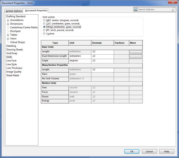
To change units, go to options, units, and change them to the units you’ll be using with PyCAM. PyCAM defaults to metric, so I always change it to MMGS:
Now that everything is in order, file -> Save As -> .DXF. You shouldn’t have any issues with scale, but if you do there is an option when saving as a DXF to force 1:1 scale output.
Next, download PyCam. I like the standalone version, which doesn’t require any installation. I’ll include a copy of that in the directory with this in case that link goes dead. Open it, and it should pop up with the default model:

In the main window, there are tabs for manipulating the model, defining tools, modifying machining processes, modifying the machining bounds, and generating toolpaths (tasks). In the visualization window you should be able to rotate the model with your mouse, as well as check overall dimensions with the “model corners” text at the top.
Now, File-> Open -> The DXF you saved from SolidWorks. You should end up with this:
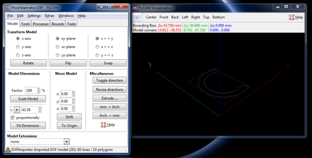
Notice how the part isn’t in the center of the coordinate system? Click To Origin to move it there. Next, we should move the model to the Z position that we want. I prefer to put the origin on the top of the material I’m cutting, so it makes it easy to zero the mill. To do so, we need to move the profile down to the bottom of the material. Since we’re using 6.35mm (0.25”) thick material, under move model type -6.35 and Shift. Also while we’re on this tab, click Revise Directions under Miscellaneous. Don’t forget to do this! If you do, you’ll get errors when trying to generate toolpaths. It should look like this now:

Also on this tab you can rotate the profile, flip it over, shift it, etc. Before we continue, make sure the model corners are correct, and that your part isn’t 50 microns across. You’d be surprised how easy it is to miss that. In this case they’re roughly 44mm by 59mm, which is correct.
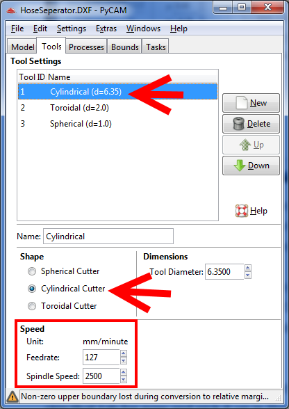
Next, we’ll configure the Tools tab. This is mostly for 3D parts, but in our case it also defines the feed and speed. The engraving operation doesn’t take into account tool diameter, so don’t worry about that. Choose the cylindrical tool and set the appropriate feed and speeds:
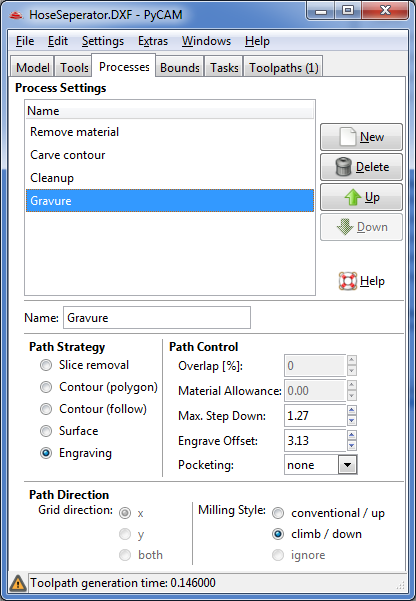
Next, click on the Process tab. We’ll be using Gravure to generate 2D paths:
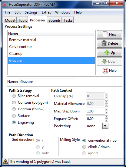
There are 4 items here we are concerned about:
Max Step Down – This is the max cutting depth per pass in mm. Since the Sherline isn’t very powerful, set this to 1.27mm (0.050”) for aluminum parts
Engrave Offset – This is how far away the toolpath will be kept from the actual part. For milling operations like this it will be half the tool diameter, or 3.125mm (.125”, using a .25” end mill)
Pocketing – How holes in the contour should be treated. Choose holes if you want to drill holes, pocket if you want to mill out the pocket, or none to just mill out the contour. Since we don’t have any holes, I’ll leave this at none
Milling Style – Determines which direction the path will be generated in (CW or CCW). For the Sherline use climb milling, as it will give you a better surface finish. If you’re interesting in learning the difference between climb and conventional milling, Here’s a good comparison.
The finished configuration should look like:
Now, click the bounds tab:
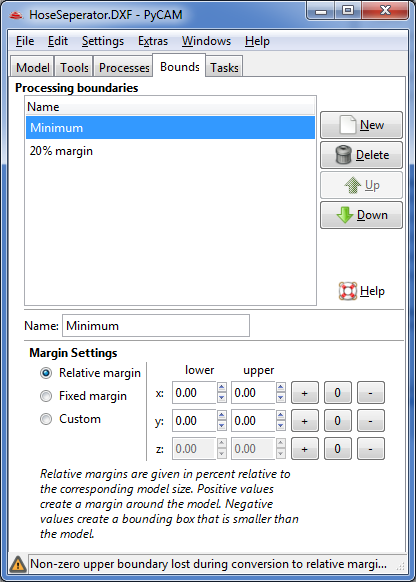
The bounds determine where the tool can go, and it will only travel within the bounds. I’ve found it can be problematic to have bounds that are too small, so I start large. Start by clicking New to create a new set of bounds, and change the relative margins to 20% in all directions:

This defines the X and Y boundaries, but not the Z (It would if we were using a 3D model). To define where we want the tool to cut in the Z direction, change the margins to Custom. The absolute value of the boundaries should be filled in from when they were set to 20%, with Z being 0 thickness (lower and upper are both -6.35). Since our material is 6.35mm thick, change the upper to 0. We should now have a box roughly shaped like the stock we’re cutting it from:

Now we’re ready to generate the toolpath, so click on the Tasks tab. Click on Gravure (Engraving), and change the Tool, Process, and Bounds to those we’ve defined. Once that’s done, click Generate Toolpath

The program should generate a tool path and list it in the Toolpaths tab:
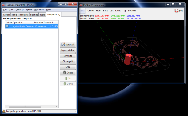
From here you can export it as a .ngc, which CNC machines should be able to open. You can also simulate the toolpaths generated to make sure the toolpath moves in the correct direction, etc. I have the “Show Drill” option turned on, which you may have to do in the settings to see the end mill (red).
Once you export the .ngc, open it with a text editor like notepad. Scan the first few lines and remove any lines that select a tool – in this case, the code is T1 M6, which specifies that we’re using tool 1. While this is a valid code, we obviously don’t have a tool changer on the Sherline, and thus LinuxCNC will get angry. Transfer the .ngc to the Sherline computer, power on the stepper motors, and open LinuxCNC(Metric-mm). LinuxCNC needs a reference before it can move the stepper motors, so click All Zero in the lower right corner.
Next, we need to secure the workpiece to the stage. I put a piece of plywood down first so when the mill breaks through the workpiece it doesn’t try and machine the stage. If possible, try and bolt the part to the stage or plywood so it doesn’t go flying when the mill “liberates” it from the material. Also, be conscious of where the clamps go – CNC machines don’t have safeties, and are more than happy to move through anything they run into. This is true for anything bolted to the stage touching any part of the mill – be careful! Below is how I secured the workpiece:
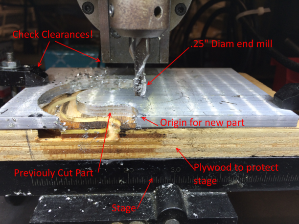
The part will be cut relative to where the origin is on the mill, which we set. We have a rough idea where the part will get cut out – notice in PyCAM where the origin is, and where the part is relative to it. If you want a very good approximation, you can print the .DXF 1:1 scale and put it on the material.
We need to zero the mill on the origin, so in LinuxCNC click on Continuous and Rapid in the lower half. Jog the mill until it’s close to where you want the origin. I usually put it where it is in the picture above – close to the edge, but not centered on it. Get X and Y where you want them by jogging them, and zeroing them individually. Zero the Z axis by turning on the spindle and slowly jogging the head down until it barely touches the workpiece – notice above how the mill left a slight mark on the part. At that point, zero the Z axis.
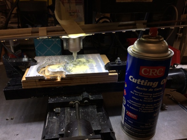
Now comes the fun part! Click on Auto, open your .ngc file, turn the spindle on and hit Run. If all goes well, it should look like this. Remember to use plenty of cutting fluid when cutting metal!
3D parts
I’ll pick up here assuming you have a 3D part modeled in Solidworks. To export as a .STL, File -> Save As… -> .STL. Make sure under options to “Output as ASCII”. This means the file will be plaintext, instead of a binary file.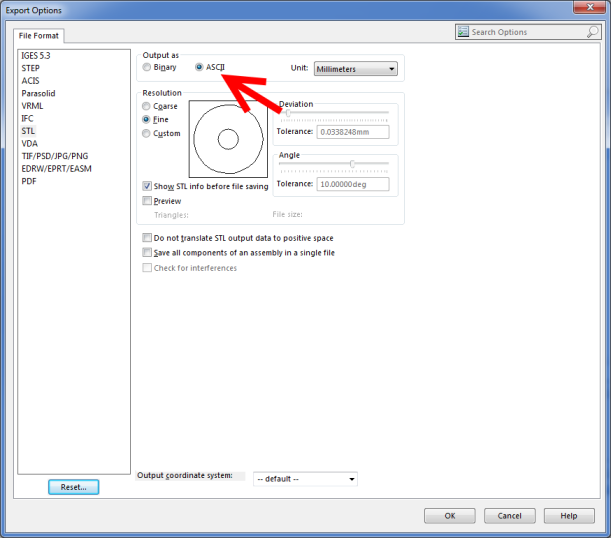
Figure 3: Save as ASCII, or PyCAM won’t be able to read the part
Since I don’t have a 3D part currently modeled, I’ll continue using the model that starts with PyCAM. So, close any instances of PyCAM you’ve got open and re-open it:
I’m going to assume you’ve already read the 2D part, so if you haven’t do so now. By default the part is located at the origin, with the origin residing at the top of the part. This is what we want, so if your part isn’t like this, use the translations to move it there.
Define the tools you have on the Tools tab, including feed and speeds for each. For most jobs you’ll want a cylindrical cutter, but if you want to put a radius on the bottom of your part (or cut any curved surfaces), you’ll want to use a spherical at some point.
On the processes tab, there are 4 types of path strategies (located at the bottom):
Slice Removal – makes large cuts to remove all material around a part. Good for roughing out a part and removing material between contours.
Contour (Polygon and follow) – Slices the part along the XY plane and generates toolpaths around the profile. For milling a strictly 2D part, I find using the Engraving option is better, but for 3D parts like the example it works well
Surface – Slices the part along the XZ or YZ plane and generates toolpaths that follow the surface. If you’re trying to make a curved surface, use this with a high overlap and ball nose end mill to make smooth surfaces.
Engraving – This is covered in the 2D section
For any of these, make the overlap high (90) for accurate toolpaths but long computation times. Play around with each to see what gives you the best results for your part – I like contour, but sometimes it swaps climb for conventional milling and vice versa, which can be bad for surface finish. This may take some trial and error, and is the hardest part about milling 3D parts.
After playing around with the settings, I used a 1mm diameter cylindrical cutter, carve contour at 60% overlap, 0 material allowance and 1.25mm max depth, and 20% margins to generate the following toolpath:
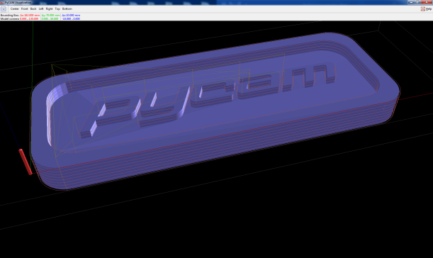
I used 60% overlap for speed of computation, but I would recommend around 90% for toolpaths that you’d actually use. Note that it only cuts out the profile of the words – not the space between them and the edge. If you actually wanted to make this, you’d also have to use a roughing pass using remove material to clear that out. I used a 1mm diameter cutter in this case which doesn’t really exist, but it’s because the part is so small. Design you parts for the tools you have J.
I hope this was helpful, Happy milling!