After reading through the Camaro’s schematics it became obvious that oil temperature wasn’t measured. The ECM transmits a value, though, which means it’s a calculated value using a model. According to Camaro owners this value is wildly inaccurate, but I also take the word of v6 Camaro owners with a grain of salt :). I wanted to measure it so down the rabbit hole I went.
The LFX’s oil pan is structural which means two things:
- It’s very thick (for an oil pan) cast aluminum and there’s not a ton of flat surfaces
- Removing it with the engine in the car is difficult at best and most likely requires pulling the engine.
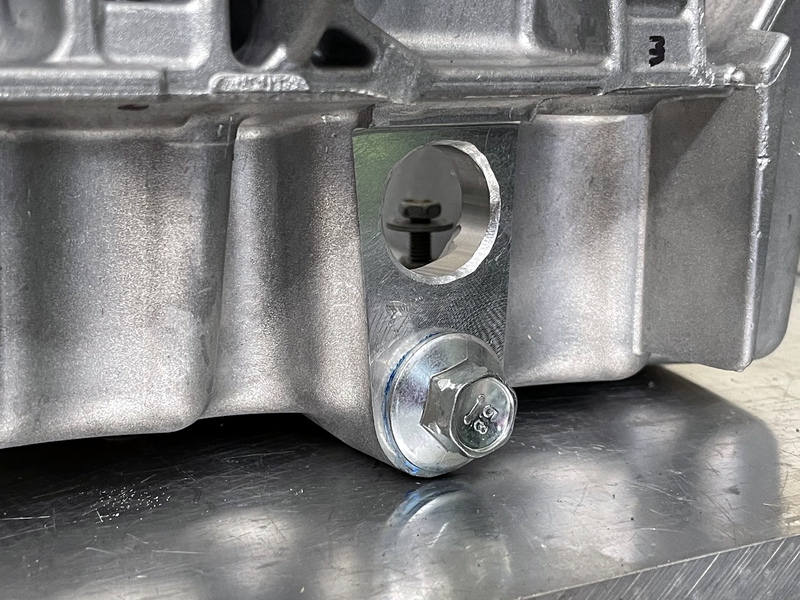
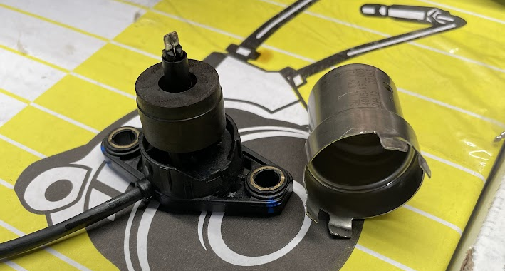
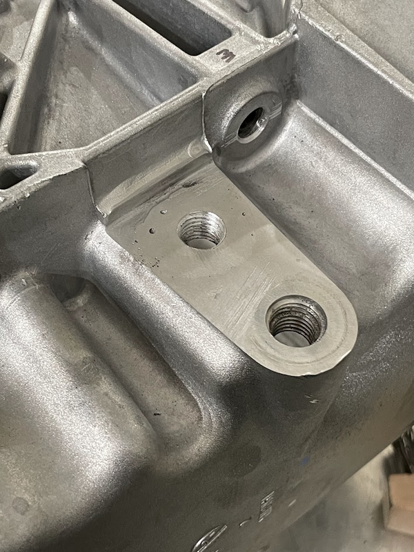
Seeing as I had the engine out of the car already I decided this was a good time to add a sensor. There’s not a ton of good spots to mount a sensor but fortunately Chevy included an oil level switch which passes through a 24mm diameter, 12mm deep hole machined into the pan. Both faces are even milled flat! I forgot to take a before picture, these show the hole after I’d added a chamfer:
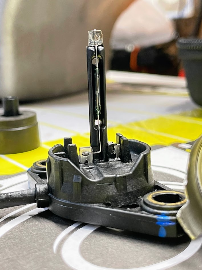
I let my curiosity get the best of me and took the oil level switch apart. It’s a reed switch with a magnetic float. The service manual calls it an “Engine Oil Level and Temperature Sensor” but it’s definitely just a on\off switch.
I did some searching online and found that Ballenger sells GM temp sensors with both m12x1.5 and 3/8″ NPT threads. They also provide the calibration info, without which the sensors are sort of useless. I chose the m12 version because NPT threads are an abomination – any time one feature does two things (clamping and sealing, in this case) it’s not good at either of them. Ballenger also sells bungs for the sensors but unfortunately they don’t fit the oil pan. I made a few when I had access to a lathe:
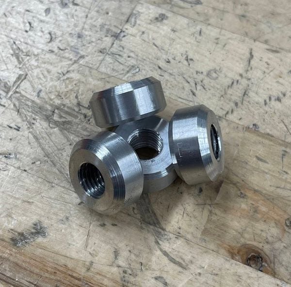
I welded the bungs in on both inner and outer joints to minimize the risk of leakage. I’d never welded cast aluminum before and for the most part it was fine, but it was kind of crazy to see how much garbage was in the metal and how much it sizzled from the porosity.
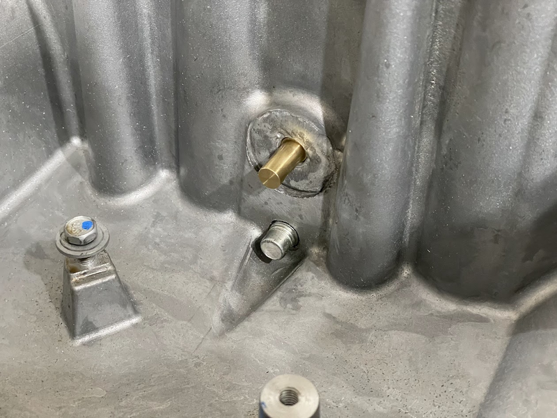
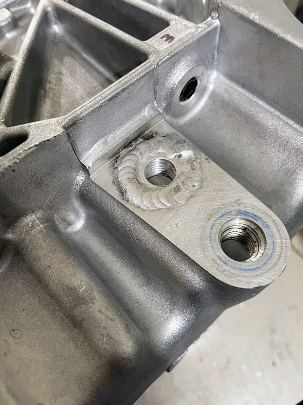
Around this point I realized I needed a flat surface to seal the sensor against since I’d used straight threads with a gasket. And that I’d covered my nice flat machined surface with weld bead. This is what I get for talking shit about NPT threads I guess :D. After a few minutes with an orbital sander I’d gotten the surface flat enough to where I’m hoping it doesn’t leak.
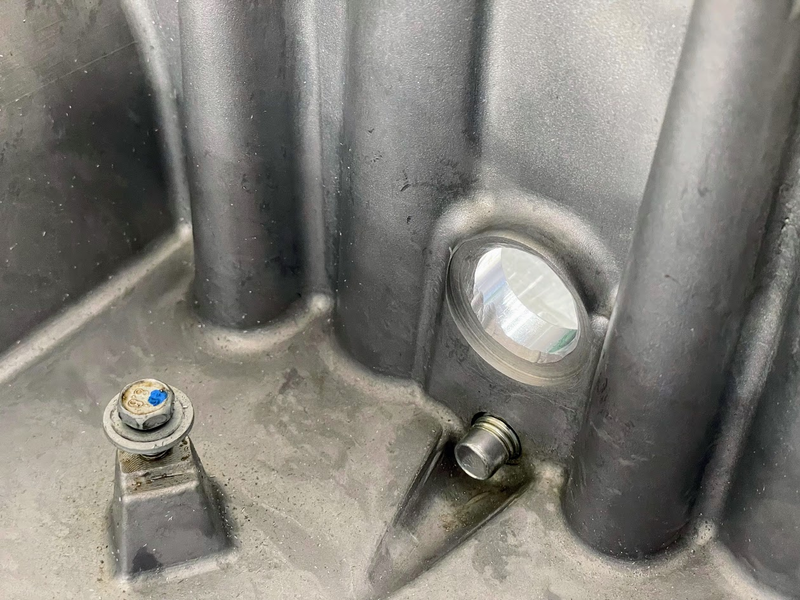
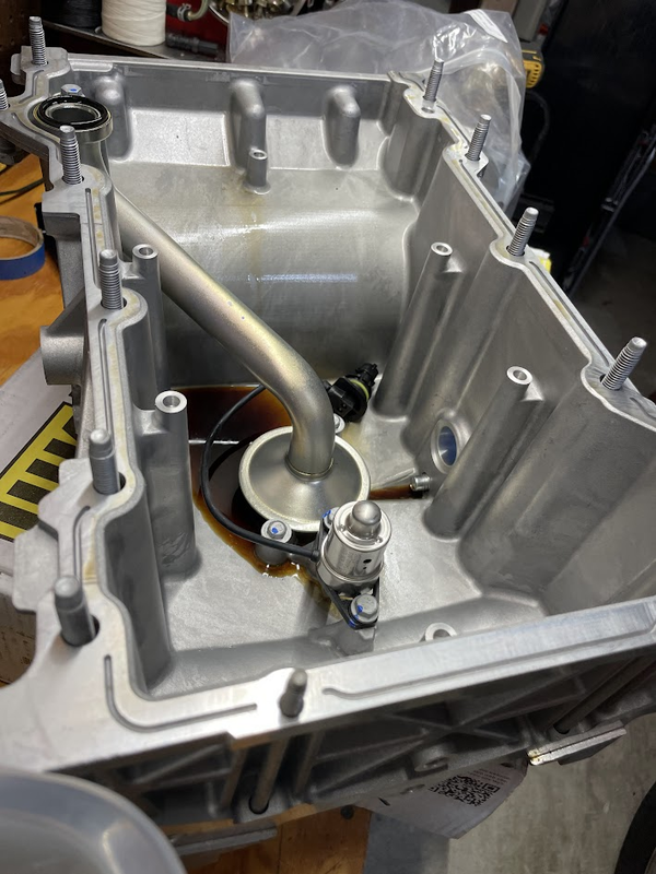
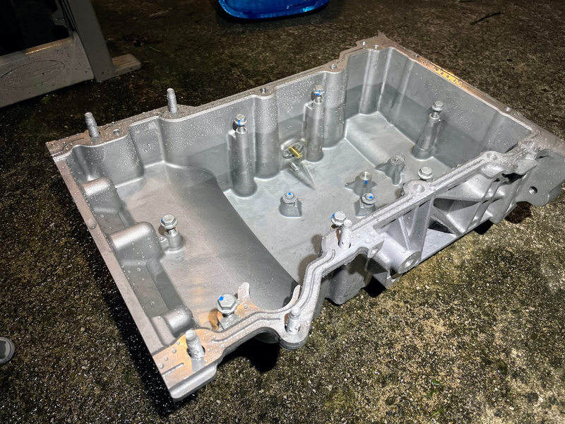
I filled the pan with 6 quarts (!) of water, there weren’t any leaks after 12 hours so it would seem that it’s fluid-tight. Also notable is the depth of oil the temp sensor and oil pickup are under. It’s a little hard to tell from the photo but they’re both under like 4-5″ of oil. No wonder people aren’t having issues with oil starvation on track!
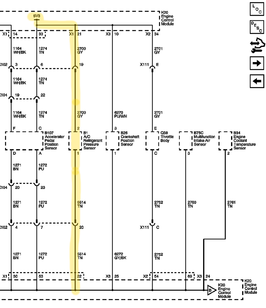
I’ll be using the AC refrigerant pressure sensor connections (5V, input, and return) with a 250 Ohm resistor to create a voltage divider with the sensor on the top side. Since the resistance versus temp is super nonlinear I created a spreadsheet to determine the calibration curve (attached). AC refrigerant pressure is transmitted on the CAN bus at 4 Hz (Message 0x3F9 bits 55-63), a third order polynomial will convert the LSBs to oil temp. Once I get everything wired up I’ll report back on if\how it works.